Near Field Supply
Kits / Instruments / Logic Boole 16
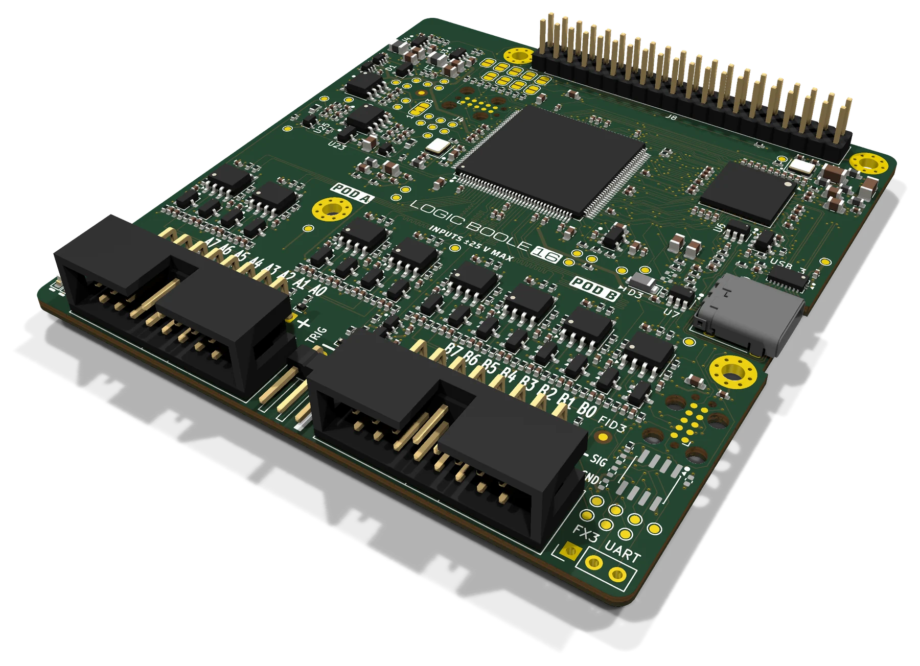
The Logic Boole 16 board at an angle: two keyed pod connectors at the front, the FPGA in the middle, USB-C on the right and a 40-pin header at the back.
Renders of the revision C design. The first five boards are built.
Kit 16 Instruments

Logic Boole 16

A 16-channel logic analyzer on USB 3. It runs from one USB-C cable on a computer, or sits on a Raspberry Pi 4 or 5 as a HAT+.

200MS/s
on all 16 channels: a sample every 5 ns, measured on the first boards
$99 $149Not on sale yet

First-batch price, one time only. The first four boards are $99. After that the board is $149.

Not on sale yet Datasheet

Ships in the United States only. Shipping and any sales tax are added at checkout. Payment is taken by Stripe: this site never sees your card.

In the box

  • The board, assembled
  • USB-C cable: not included. Use one made for USB 3
  • Spacers and screws for a Raspberry Pi: not included. It takes 4 × M2.5 × 16 mm spacers and 8 × M2.5 × 6 mm screws
  • Probe leads: not included
01

What it does

Measured with 3.3 V signals unless marked
16
channels in two pods of 8, each pod with its own threshold
85MHz
clocks captured whole, on each of the 16 inputs of one board
0.3–3V
threshold for each pod in 0.75 mV steps, so one capture can hold two logic voltages
75–80ns
from the trigger sample to the trigger output, to start a scope
1MΩ / 10pF
at the probe pin, on every channel
±25V
on any input, powered or not

A trigger in the FPGA

The trigger runs on every sample at the full rate: edges, levels, pulses by their length and levels that have lasted, with up to four stages in turn. A trigger input lets another instrument start the capture.

Each channel has a glitch filter up to 1.25 µs in 5 ns steps, and a capture can sample on your circuit's own clock up to 50 MHz.

It streams as it samples

Samples go to the host over USB 3 as they are taken, so a capture's length is set by the host's memory. The longest capture so far is 600 million samples.

All 16 channels stream at 100 MS/s for any signal, and at 200 MS/s for signals that change in up to 96 million samples a second.

02

Find your way around

Everything you plug into is on an edge
Front of the Logic Boole 16 board, labelledFront of the Logic Boole 16 board, labelled: 40-pin stacking header; Pi bus jumpers; Power from USB or the Pi; A threshold for each pod; 16 fast comparators; Status LEDs; Pod A: channels A0–A7; 4 × M2.5 mounting holes; Infineon FX3; Spartan-6 FPGA; USB-C; Inputs rated ±25 V; Trigger in and out; Pod B: channels B0–B7. 40-pin stacking header The Pi's pins pass through to the top Pi bus jumpers Optional: tap the Pi's I²C, SPI and UART Power from USB or the Pi Ideal diodes. It never feeds the Pi A threshold for each pod 0.3–3 V, pod A and pod B set separately 16 fast comparators Hysteresis on every channel Status LEDs Power, armed, triggered Pod A: channels A0–A7 Keyed, a ground beside every signal 4 × M2.5 mounting holes On the Pi's pattern, for M2.5 spacers Infineon FX3 USB 3 at 5 Gbit/s, USB 2.0 as a fallback Spartan-6 FPGA Samples at 200 MS/s, triggers in hardware USB-C Power and data on one cable, either way up Inputs rated ±25 V Divider, clamp and ESD diode on each Trigger in and out 3.3 V logic. The input tolerates 5 V Pod B: channels B0–B7 Its own threshold: two logic levels at once
1234567891011121314
  1. 1
    40-pin stacking headerThe Pi's pins pass through to the top
  2. 2
    Pi bus jumpersOptional: tap the Pi's I²C, SPI and UART
  3. 3
    Power from USB or the PiIdeal diodes. It never feeds the Pi
  4. 4
    A threshold for each pod0.3–3 V, pod A and pod B set separately
  5. 5
    16 fast comparatorsHysteresis on every channel
  6. 6
    Status LEDsPower, armed, triggered
  7. 7
    Pod A: channels A0–A7Keyed, a ground beside every signal
  8. 8
    4 × M2.5 mounting holesOn the Pi's pattern, for M2.5 spacers
  9. 9
    Infineon FX3USB 3 at 5 Gbit/s, USB 2.0 as a fallback
  10. 10
    Spartan-6 FPGASamples at 200 MS/s, triggers in hardware
  11. 11
    USB-CPower and data on one cable, either way up
  12. 12
    Inputs rated ±25 VDivider, clamp and ESD diode on each
  13. 13
    Trigger in and out3.3 V logic. The input tolerates 5 V
  14. 14
    Pod B: channels B0–B7Its own threshold: two logic levels at once
The front of the board.
03

The software

macOS and Linux. Not Windows
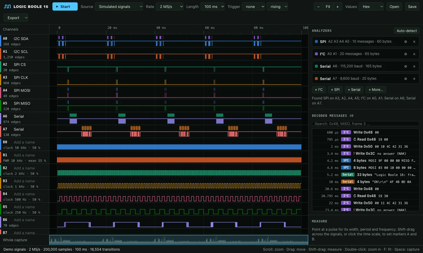
The app in a browser: sixteen channels of waveforms, and the analyzers it found with the messages they decoded.
The app, here showing its built-in demo signals, which need no board.
01

The app

Opens in your browser: waveforms, a threshold for each pod, the trigger, and decoders for I²C, SPI and serial that it can find by itself.

02

Command line and Python

Capture to a file for PulseView, a waveform viewer or a spreadsheet. Run any of sigrok's decoders on a capture. Commands print JSON for scripts.

03

AI agents

An agent can use the board by itself, through the command line with a skill file or through a Model Context Protocol server.

# Check the computer and the board
./logicboole check

# Wait for B0 to fall, and keep the millisecond after it
./logicboole capture reset.sr --rate 200M --time 1ms --trigger "B0=f"

# What a protocol decoder finds in a saved capture
./logicboole decode bus.lb16 i2c scl=A1 sda=A0
04

On a Raspberry Pi

A HAT+ for the Pi 4 and Pi 5
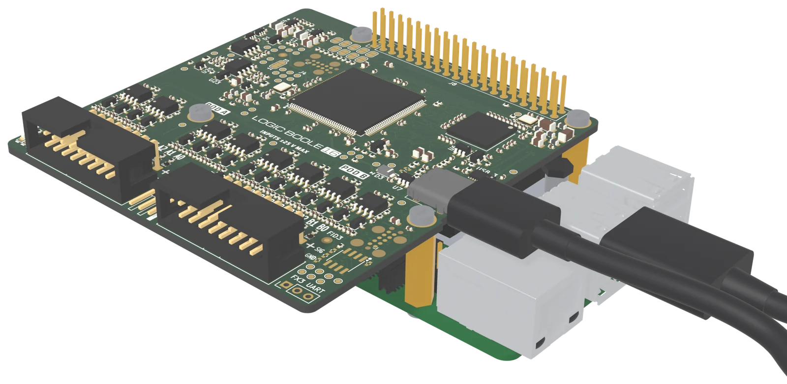
The board mounted on a Raspberry Pi 5 on four spacers, with a short USB cable from the board to one of the Pi's USB ports.
On a Raspberry Pi 5, with the link cable to the Pi's USB 3 port. A render. The spacers, the screws and the cable are yours to supply.
  • Stack another HAT on top. As shipped the board connects to none of GPIO 2 to 27, and all 40 pins pass through.
  • Powered by either side. It runs from the Pi's 5 V pins, from USB-C, or both, and never feeds power back into the Pi.
  • Capture the Pi's own buses. Close solder jumpers, and a capture can take the Pi's I²C, UART and SPI lines in place of pod channels.
  • Room for the Active Cooler. The board sits 16 mm above the Pi, and nothing but the header is fitted underneath.
05

Specifications

Board revision C · datasheet revision C

Capture

Channels16 digital, in two pods of 8
Sample rate200 MS/s, or 200 MS/s divided by a whole number
Streaming, USB 3Raw: 16 channels at 100 MS/s, any signal. Run-length: 16 channels at 200 MS/s, for signals that change in up to 96 million samples a second
Fastest signalClocks up to 85 MHz, pulses down to 6 ns
Before the triggerThe newest 8184 words: 16,368 samples in the raw format
Trigger headerTRIG IN, and TRIG OUT 75 to 80 ns after the trigger sample
Glitch filterFor each channel, from off to 1.25 µs in 5 ns steps
Capture clockThe circuit's own clock, up to 50 MHz

Inputs, link and board

Logic levels1.2 to 5 V
Thresholds0.3 to 3.0 V in 0.75 mV steps, one for each pod
Channel skew1.4 ns between the earliest and the latest of the 16 inputs of one board
Maximum input±25 V
Host linkUSB-C. USB 3 at 5 Gbit/s; USB 2.0 works and carries a ninth as much
Power5 V from USB-C or the Pi's header, about 1 W
Main partsSpartan-6 XC6SLX9 FPGA, Infineon EZ-USB FX3, 16 fast comparators
Size82 × 86 mm, four layers, parts on the top side only
06

Open hardware

Read it, change it, build your own
Open hardwareCERN-OHL-S v2
SoftwareGPL-3.0-or-later
FirmwareMIT

One repository holds the whole of board revision C: the KiCad project and the files the boards were made from, the FPGA design in Verilog with its test benches, the firmware's source, and the host software.

The board keeps no firmware. The host loads it each time it connects, so nothing you load can brick it.

View on GitHub

What is not open. The built firmware image also holds code of Infineon's FX3 SDK libraries, which stays under Infineon's license: the software downloads the image once. The name Logic Boole and its logo are not part of the licenses.
07

Good to know

Before you pack it
08

From the field guide

Near Field Notes: the notes behind this board