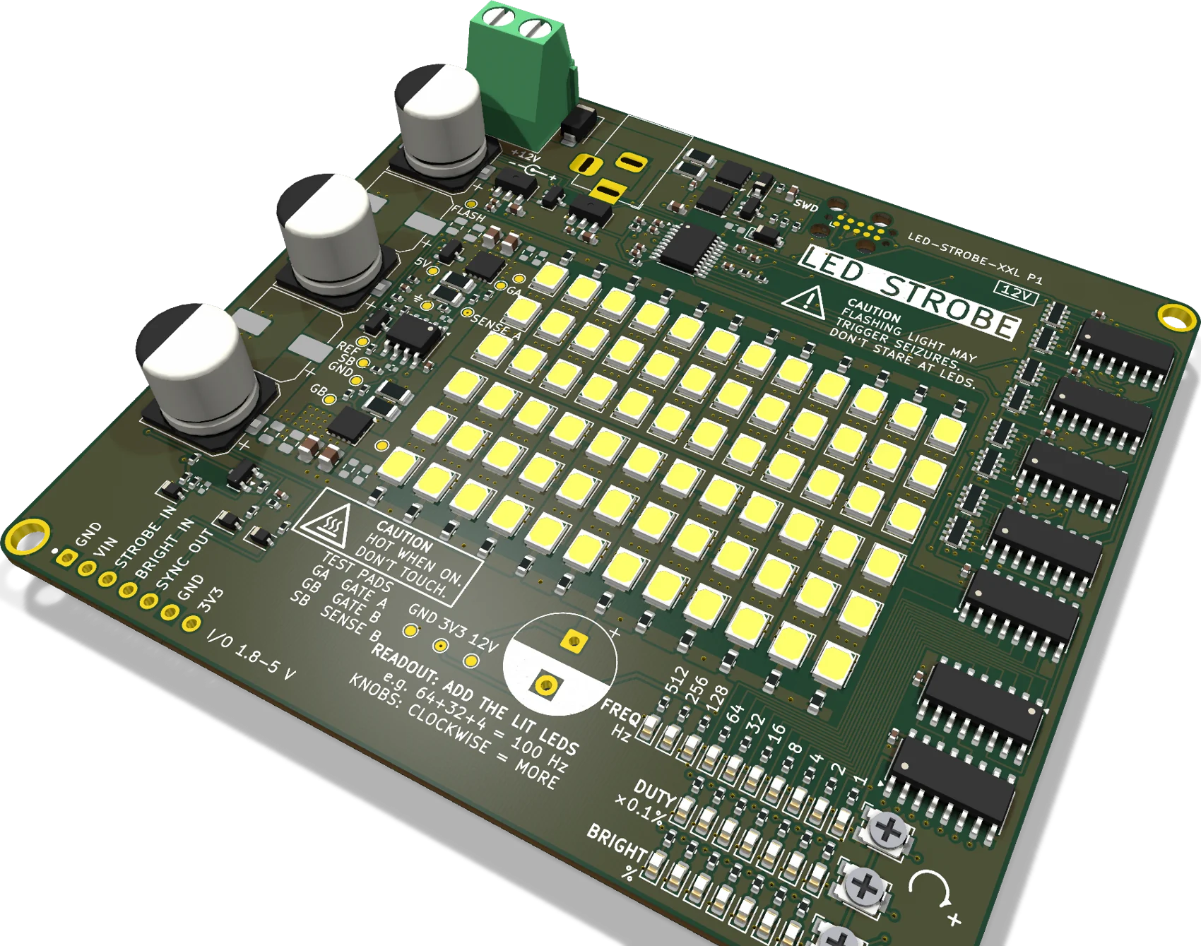
A 72-LED white strobe on one board. Set the rate, the flash length and the brightness with a screwdriver. It needs only 12 V: no code and no computer.
All three warnings are printed on the board.
A timer in the microcontroller starts and ends each flash, so a stuck program cannot leave the LEDs on. Two op-amp constant-current drivers hold the LED current steady as the 12 V droops.
Three 1,000 µF capacitors on the board supply the short flashes, which is why a plain 12 V, 1 A adapter is enough for most strobe use.
A temperature sensor sits beside a driver MOSFET. The firmware keeps the board inside its heat limits by dimming the flashes, and the BRIGHT row of the readout shows what it has done.
Measured in still air with no heatsink: at 1,000 Hz and 7.5 % duty the board held full brightness, and the sensor leveled at 41 °C.
Turn it with a small screwdriver; clockwise is more. The rate trimmer follows a log curve, so 1 Hz and 1,000 Hz are both easy to land on.
Binary pads on the back: 10 for the rate in 1 Hz steps, 7 for the duty in 0.1 % steps, 7 for the brightness. Bridge the pads that add up to the value you want, and it cannot drift or get knocked.
STROBE IN and BRIGHT IN on the 7-pin header take 1.8 to 5 V logic. Fire flashes from a camera, a sound or light sensor, or any microcontroller.
| Jumper open | The trimmer. Every board ships this way and is tested on its trimmers |
|---|---|
| GND to PADS | That setting's solder pads on the back |
| GND to PIN | That setting's header pin |
| Both sides | An error: its readout row blinks and the trimmer stays in charge |
One solder jumper on the back for each setting.
Three rows of red LEDs show, in binary, what the board is doing right now, whatever the source. The value of each LED is printed above its column.
The header carries GND, VIN, STROBE IN, BRIGHT IN, SYNC OUT, GND and 3V3. STROBE IN is active when it is pulled low, by a contact to GND or a logic low. What it does depends on which settings you put on PIN.
| Pin | Mode | What it does |
|---|---|---|
| STROBE IN | Trigger | Rate on PIN: each time the pin goes low, the board fires one flash, started in hardware. A bouncing contact gives one flash. Up to about 1,100 flashes a second. |
| STROBE IN | Follow | Rate and duty on PIN: the LEDs are on for as long as the pin is held low. A light held longer than about 20 ms dims as the drivers heat. |
| STROBE IN | Duty | Duty on PIN: the board measures the pin's duty and flashes at its own rate. PWM from 100 Hz to 100 kHz, most accurate below 20 kHz. |
| BRIGHT IN | Brightness | 0 to 3.3 V sets 0 to 100 %, or send PWM at any logic level and the board measures its duty. |
| SYNC OUT | Sync | 3.3 V logic, low during every flash. Trigger a camera or a scope from it. |
Shine it on a fan, a spindle or a printer part and turn the rate down from the top until it first stands still. The rate times 60 is its speed.
25 Hz → 1,500 RPMMatch the rate to a fan, a gear, a belt or a speaker cone and it stands still. Nudge the rate off and it turns in slow motion.
Duty 0.5 %A dark room, a camera on a tripod, an exposure of a second or two: a bouncing ball shows up once for every flash. Mind the seizure warning.
20 Hz, duty 0.5 %Flash in step with dripping water and the drops hang in the air, or crawl upward.
Rate tuned to the drip rateLight the part only while the camera exposes. SYNC OUT fires the camera's trigger on every flash.
SYNC OUT → camera triggerSYNC OUT on one scope channel, your photodiode or sensor on the other. The gap between them is its response time.
SYNC OUT low = light onWire the camera's flash-sync contact to STROBE IN and every shot gets one short flash, its length set by the duty trimmer.
Sync contact → STROBE INOne short flash for each trigger from a sound or light sensor freezes a balloon pop or a splash.
Trigger modeCamera flash and high-speed photos fire flashes from STROBE IN, with a solder jumper on the back set to PIN. Everything else needs only the trimmers. Section 8 of the datasheet gives starting settings and wiring for each.
| LEDs | 72 white, 6500 K, CRI 80, in 24 strings of 3 |
|---|---|
| LED current | 4.32 A at full brightness, 180 mA a string |
| Peak light | About 5,800 lm, from the LED datasheet's lowest brightness grade |
| Flash rate | 1 to 1,000 Hz free-running; up to 1,100 Hz triggered from STROBE IN |
| Duty | 0.1 to 12.7 % in 0.1 % steps |
| Flash length | 5 µs to 127 ms |
| Brightness | 128 steps, linear in current |
| Trigger delay | 3 µs at most from STROBE IN to SYNC OUT, timed by a Raspberry Pi Pico |
| Supply | 12 V DC on a 2-pin screw terminal. The firmware pauses flashing outside 10.5 to 14 V |
|---|---|
| Supply current | 0.30 A average, up to 4.5 A in long flashes |
| Protection | Reverse polarity, a cut-off at about 14.9 V (measured), a 24 V surge diode, ESD diodes on the header signals |
| Heat limits | Dims from 50 °C at the sensor, stops at 60 °C and restarts by itself |
| Header | 7-pin 0.1": STROBE IN, BRIGHT IN, SYNC OUT, VIN, 3V3, 2 × GND |
| Logic levels | 1.8 to 5 V on the inputs. SYNC OUT is 3.3 V |
| Main parts | PY32F002B microcontroller, TLV9062 op-amp, 2 × AON7400A MOSFETs |
| Size | 96.5 × 86.4 mm, two layers, four M3 holes, flat back |
Three 1,000 µF capacitors feed every short flash on this board.
Note 19 · SensingThis board senses its LED current on the low side.
Note 37 · PowerRead before you pick a supply for it.